WMS Wideband Resources
Important Message!
We no longer sell the WMS Wideband O2 system or Wideband parts as there are too many low cost off shore systems on the market.
You can purchase a new wideband sensor from your local Volkswagen Dealership, Part #021-906-262B or Bosch Part # 025 800 705 7
- Installation Manual (pdf | 526KB)
- Software Manual (pdf | 411KB)
- Operating Software (standard version) (exe | 2.97MB)
- Operating Software (without installer) (zip | 2.0 MB)
Installation
1. Find a suitable mounting place for the WMS Wideband O2 Control Box, where the easy-to-read display is visible. It can be mounted on the dash or panel by cutting a hole for the small plug and mounting with double sided tape.
2. The Main Harness runs from the Control Box out to the O2 Sensor in the exhaust. Route the harness from the location of the sensor on the exhaust to the Control Box through a suitable grommet in the firewall.
Note: the plug for the Control Box is much smaller than the O2 Sensor plug and is easier to fit through a grommet. Be sure the harness has clearance from the hot exhaust and other moving engine parts.
3. The following wires can be found on the Main Wiring Harness
Note: only the red and black wires need to be hooked up for the system to operate.
- Red - 12V+ ignition power. Be sure this is 12V power when the ignition is turned on only. There is a noise suppression diode in the red wire, be sure to leave this inline, do not cut the wire short before this.
- Black - Chassis Ground
- White- 0 to 1 Volt signal. This wire simulates a stock O2 sensor for factory computers. If you are using a factory computer or other system that uses a narrow band O2 sensor signal you will hook this wire up to the factory O2 sensor signal wire. See Narrow Band Simulation section for more information on wiring.
- Orange - RPM signal input. This wire is used with our datalogging software to log rpm with the AFR. See the RPM Signal section for further information.
- Purple - 0 to 5 Volt signal. This signal is standard for most external datalogging systems such as those used on chassis dynos or other onboard loggers.
- Green - Analog Ground. This provides a ground reference to the datalogging system when the purple 0 to 5 Volt signal is used
4. Carefully plug the Control Box into the Main Harness.
5. Mount the Bosch Wideband O2 sensor in a suitable location in the exhaust. Generally, if you are replacing a factory O2 sensor the factory location will be good. See O2 Sensor Location for further information if you are doing a custom mounting of the sensor.
Note: anti-seize compound should be used on the O2 sensor threads so it can be removed at a later date.
6. Carefully plug the O2 sensor into the Main Harness.
7. Turn on the ignition. The red light behind the WMS logo should light up if the unit has power.
O2 Sensor Location
Sensor must be mounted between the engine and the catalytic converters (in application where they are used). If no catalytic converters are used, then the sensor should be close to the hedder collector, where the exhaust is hot and each cylinder is represented.
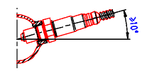 The O2
sensor must be installed in the side or top of the exhaust pipe. The installation angle of the Bosch wideband O2 sensor should be
inclined at least 10° towards horizontal (electrical connection upwards). Thus preventing the collection of liquids between sensor
housing and sensor element during the cold start phase.
Tightening torque: 40-60 Nm (29-44 ft-lbs). Material characteristics and strength of the thread must be appropriate (Source: Bosch Y 258 K01 005-000e).
On turbo applications install the sensor after the turbo and before the catalytic converter. The high exhaust pressure before the turbo interferes with the measurement and the high exhaust temperatures encountered can damage the sensor.
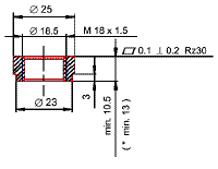 Most
factory O2 sensor locations are acceptable for the wideband sensor but be sure they follow the general guidelines above. If you
require a bung to weld in the exhaust they are available from K&N - part # 85-21688. Bung specifications are also given in this
drawing from Bosch (click image to enlarge image).
Under-floor installation of the sensor at a distance from the engine requires an additional check of the following points: a) positioning of the sensor with respect to stone impact hazard, b) positioning and fixing of cable and connector with respect to mechanical damage, cable bending stress and thermal stress. The sensor must not be exposed to strong mechanical shocks (e.g. while the sensor is installed). Otherwise the sensor element may crack without visible damage to the sensor housing (Source: Bosch Y 258 K01 005-000e).
Operation of the System
When the ignition is turned on the status led will light up, this will indicate what the system is doing.
- Blinking Green - The sensor is on but the engine is not running. The sensor detects a rise in voltage when the engine is started and will start heating the sensor then.
- Blinking Red - Engine has started and sensor is warming up. The sensor should warm up within 30 seconds, if not there is a problem. If no sensor is plugged in the light will continue to blink red.
- Solid Green - Sensor is ready, the LED display will light up and read an accurate AFR.
- Solid Red - Problem with the heating circuit in the sensor. This could be caused by a bad sensor, exhaust that is too cold or too hot.
The WMS Wideband Controller uses a voltage sensor to determine when the engine is running to start heating the sensor, this increases sensor life. The sensor must see 13.3 volts to start heating, if it does not the status led will continue to blink green and no AFR will display. If you have a low output alternator or low voltage this may prevent the sensor from working. If this is a problem give us a call and we can solve this for you.
Narrow Band Simulation
To connect the WMS Wideband white wire to an EFI-computer follow the instructions below, depending on what type of O2 sensor is being used. Many EFI computers, especially factory computers, use the narrow band as one of its main sensors and must be retained for proper operation.
- 1-wire O2 sensor - White wideband wire goes directly to the signal wire.
- 2-wire O2 sensor - With engine off, measure resistance between each wire and the sensor body. The low resistance wire is the heater power for the sensor. Connect the white wideband wire directly to the other wire. Leave the heater power wire unconnected.
- 3-wire O2 sensor - Typically the 3 wires are heater power, ground and signal and are 2 white wires with 1 black wire.
Connect the white wideband wire to the black wire (signal) going to the EFI computer. Leave the other wires unconnected.
If the wiring colors are different:
- Heater power: 12V or more with engine running
- Ground: low resistance to chassis ground with engine off.
- Signal: The signal wire should fluctuate around 0.45V when the engine is warmed up. Connect the white wideband wire to this wire.
- 4-wire O2 sensor - connect the same as the 3 wire sensor above, there is one additional ground in a 4 wire sensor.
Some EFI-computers will create a fault when the heater power wires of the oxygen sensor are disconnected. In this case it is easiest to leave the stock O2 sensor where it is and weld in a new O2 bung for the wideband (see O2 Sensor location for more information). Leave the heater wires connected to the stock sensor so no fault codes are set.
Download
Click here to download installation manual (pdf | 526KB)
* Caution *
The oxygen sensor is heated and gets very hot when powered or when in the exhaust. Do not touch the hot sensor. Do not let a hot sensor touch a combustible surface or use near flammable liquids or gases. Failure to follow these warnings may result in severe burns, explosions or fires.
When installed in the exhaust, the oxygen sensor MUST be connected and powered by the WMS Wideband control box whenever the car is running. An un-powered oxygen sensor will be quickly damaged when exposed to hot exhaust gases.
Calibration of the Sensor
No external calibration of the sensor is required. This function is controlled by the Bosch calibration chip in the WMS Wideband Control box. Other systems may require the user to do a frequent 'free air' calibration, but such systems are far less accurate.
Leaded Fuel Warning
DO NOT use the sensor with engines that burn leaded gasoline. Any O2 Sensor, including the Bosch Wideband sensor, do not function well with leaded gasoline, which will permanently damaged the sensor even after a short period of use .If you do need use the WMS Wideband O2 with leaded gasoline do as few runs as possible and remove it from the exhaust immediately after use.
Depending on the lead contents of the used fuel the expected service life time is (Source: Bosch Y 258 K01 005-000e):
Operating Software
How To Use
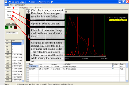
After downloading the software and loading it on your computer, open the program (screenshots below) and do the following:
- 1. Click on "File" and then "New"
- 2. Select a new folder in which to save your data. Note: Don't save to same folder as other data files or they will be overwritten.
- 3. Type in a file name for the notes to be saved as and click "OK."
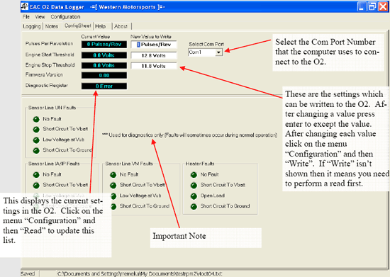
- 4. Select com port number on the "ConfigSheet" tab
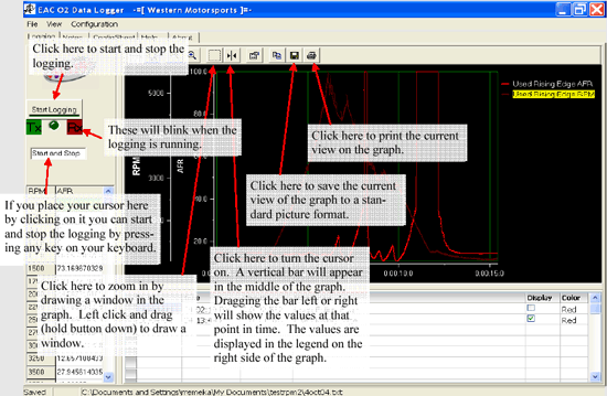
- 5. Plug in the O2 Sensor and click "Start Logging"
- 6. Click button again now marked "Stop Logging"
- 7. You can change the description and the color of this record.
- 8. Click on the "Notes" tab to write down any info for all data sets.
- 9. Click on the "Logging" tab and select "Save"
- 10. This will save the notes description and color.
- 11. You can record up to 15 runs before needing to create a new folder.
- 12. The buttons on top of the graph can be used to "Zoom," "Save" or "Print" the graph
- 13. The sixth button from the left is a cursor used to display the value at a specific time or RPM.
- 14. You can click and drag this line to anywhere on the graph.
Download Software
Download the software here; version 1.4.0.1 (exe | 2.97MB)
Screenshots
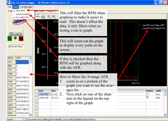
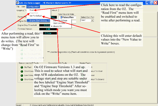
Below are a number of screenshots of the operating software. Information windows have been added explaining the commands and functions of the software.
